The AllScan UCI200 USB Communications Interface is a professional-grade USB interface that connects a radio, mic, speaker and USB host device, with unprecedented flexibility, setting a new standard for AllStar, DVSwitch, EchoLink and other Radio-Over-IP (ROIP) applications. The UCI200 is the world's first multi-mode USB interface product designed and optimized for use with ham and commercial mobile radios that also directly supports communications microphones, speakers and other audio equipment. Within AllStar and EchoLink, Audio+PTT interfaces are most commonly referred to as URIs (USB Radio Interfaces), but because the UCI200 also connects to communications mics and speakers, USB Communications Interface (UCI) is a more general term.
Schematic (Main Board) /
Schematic (Analog Board) /
Schematic (Mic Adapter Boards)
Enclosure size: 3.46"W x 1.5"H x 3.94"D (88x38x100mm). Click images to enlarge
Introduction
My main product development goal is to create innovative full-featured products that support a wide range of applications. For example the AllScan URI125 integrates all functions of 2 previous products, the URI101 and URI110, resulting in a USB Radio Interface that supports multiple types of radios in the same form factor and around the same price point. This makes the choice of which product to get easier for buyers and simplifies inventory and configuration management.
Prior to the UCI200 there were 2 separate classes of interfaces used with AllStar and other ROIP apps – either USB Radio Interfaces, or Radio-less interfaces that connect to a mic and speaker. Each has its advantages and each has very different design requirements. Supporting both of these modes in one device can provide major advantages, but USB interfaces in the past have been very simplistic, accommodating one type of interface only. In fact, prior to the introduction of the UCI120 in Sept. 2024, there had never been a professional-grade radio-less USB interface with similar functions – at least not at anywhere near the same price point. It was only natural that the next step in the AllScan UCI product line would add an additional dimension to the interfaces supported and the ways they can be used.
Prior to these innovations some major limitations existed in how nodes could be used. For a simple low-cost node these limitations are typically not a concern and there has so far been a sort of assumption that nodes just do one thing, but some use cases are more complex than others and there was a definite need for a more flexible and comprehensive interface. To fully understand this let's look at a common set of use cases – using a mobile radio in a way that supports:
- Normal operation with local repeaters
- Connection to AllStar (or other ROIP network) such that an HT can be used to access the network through the mobile radio
- Connecting directly to AllStar with the radio's mic and a speaker, such that when preferred the mic can be used instead of needing to use an HT to transmit to a mobile radio that's only a few feet away
- Talking on local RF while also being connected to AllStar eg. so you can use the mic and speaker to talk on AllStar and RF, while other hams at a nearby park bench, hamfest, club meeting or community service event can join the QSO on HTs
During a Ham Radio Workbench podcast I was on in Dec. '25, Mark N6MTS shared an all too common example of numerous RF transceivers and connections being needed just to get an audio signal to travel a few feet. When on a roadtrip and wanting to talk on DMR but being out of range of DMR repeaters most of the time he resorted to using a cellphone to provide WiFi to a DMR hotspot which in turn provided an RF link to an HT. Thus 3 separate RF transceivers needed to be used (cellular data, WiFi, and VHF/UHF), all inside of a vehicle. Now add the power and interconnect cables, battery chargers, etc. and the result is a hodgepodge of devices, cabling and RF signals in the vehicle.
To avoid such a situation, a radio-less interface such as the UCI90 and a K1 speaker-mic can be used, which is a far simpler and more compact solution. A radio-less node is not as flexible as a radio node / hotspot though, for example if when on a roadtrip you wanted to leave the node in the car and go for a walk with an HT, a separate radio node in the vehicle would be needed.
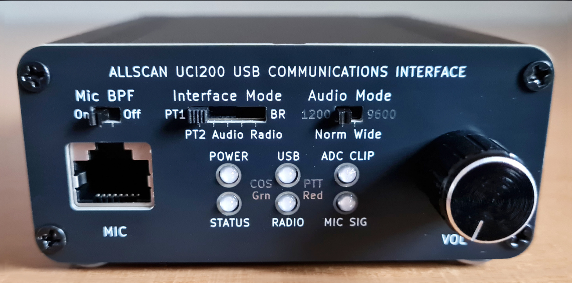
The UCI200 is the first USB interface that not only supports Radio and Radio-less interface modes, but also supports 2 Pass-Thru modes enabling the mic to be directly connected to the radio, and supports a Bridge mode allowing the radio, the mic and speaker to be simultaneously connected to the USB host.
With the UCI200 the 4 use cases mentioned above are now all easily supported with a single front-panel slide switch. Before the UCI200, to support those uses would have required manually unplugging the mic and moving it back and forth between the radio and other devices and/or having multiple interfaces and/or mics, radios, cables, antennas, switchboxes, etc.
To fully support a wide range of mics and radios required yet another industry-leading innovation – the integration of the AllScan MA1 Mic Adapter into the UCI200, and creation of an open-source hardware standard for small 10×18mm adapter PCBs that allow literally any brand or model of communications mic to be plugged in, supplied with any DC Supply Voltage from 5-14V and/or any Mic Bias source from 2V/2KΩ to 5-14V/600Ω while also passing through button-press/serial data lines to a secondary RJ45 jack that connects to the radio's mic jack such that the mic keypad functions can be used as normal with the radio to enter frequencies, select channels or send DTMF tones.
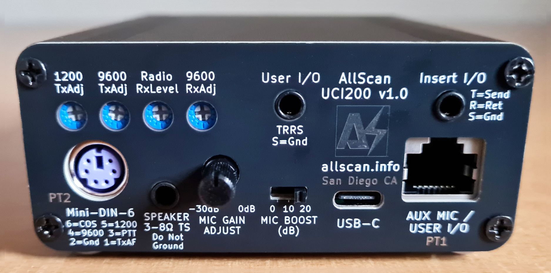
The UCI200 supports 2 Pass-Thru modes, PT1 which directly passes the mic lines to the 2nd RJ45 to the radio, and PT2 which passes the mic audio and PTT to the radio through the Mini-DIN-6 jack. All modes other than PT1 enable the 2nd RJ45 jack to be used as an additional mic input eg. for a headset mic, or as a User I/O jack that can bring any of the 20+ lines available on the internal PCB header pads to the back panel.
Because the UCI200 supports the use of radios with a Mini-DIN jack – which have both "1200" (Speaker) and "9600" (Preemphasized, Flat) audio I/Os, and because the UCI200 is the first product that enables a mic signal to be directly routed to a Mini-DIN jack (after being amplified, filtered and limited), this implied it should also support selectable mic preemphasis and speaker audio deemphasis. Not everyone uses the 9600 I/Os but because AllStar does support preemphasized audio, it would have limited AllStar's functionality if the UCI200 only supported the 1200 I/Os.
The UCI200's support for flat audio also enables it to be interfaced to repeater systems, where it can link a repeater to AllStar (ie. at the repeater site, with hardwired Ethernet provided to the USB host) while also supporting a local mic and speaker, and can be used in 4 different modes, enabling a repeater to be connected just to the mic and speaker (Pass-Thru), or to AllStar only (Radio), or to both (Bridge), or for the mic and speaker to be connected to AllStar only and not to the repeater (Radio-less).
The UCI200 can also accommodate numerous other use cases not mentioned above, for example digital data/packet modes, use with HF rigs, FreeDV, etc.
Features
- Multi-Mode USB Interface supporting multiple audio paths (USB, Mic & Speaker, Radio) and the following Interface Modes:
1. Pass-thru Mic (PT1): Mic in → Aux Mic out, Radio Rx → Speaker out
2. Pass-thru MD6 (PT2): Mic in → Radio Tx, Radio Rx → Speaker out
3. Audio (Radio-less): Mic in → USB out, USB in → Speaker out
4. Radio: Radio Rx → USB out, USB in → Radio Tx
5. Bridge: Above connections (2)-(4) are simultaneously enabled
- Supports the following Audio Modes:
1. Norm / 1200: Normal audio as typically used with mic & speaker I/Os
2. Wide / 9600 (Flat): Preemphasized unfiltered audio typically with a 0-4.8KHz bandwidth. Enables the Mini-DIN-6 9600 output and mic preemphasis and speaker deemphasis
- 6dB/octave bandpass filter ahead of the AGC mic preamp, and switchable 6dB/oct Mic BPF after the AGC minimize AGC gain-pumping, ADC clipping, thumps, clicks and other background noise. These filters have a smooth response curve supporting extended frequency response for other audio applications
- Supports AllStarLink, DVSwitch, HamVOIP, EchoLink, and works as a standard audio interface in Windows, Mac & Linux. Includes a C-Media CM108B IC, USB-C jack, Analog Devices MAX9814 Mic Preamp & AGC, and internal header pads for all Radio & CM108 I/Os
- RFI filtering on all I/Os, optimized PCB layout with separate analog and digital power supplies and ground planes ensures extremely low noise and clear audio. Extruded aluminum enclosure maximizes durability and EMI/RFI resistance
- 6 tri-color status LEDs show status of Power, Mic signal, ADC Clip, and PTT & COS for each audio path. The signal and clip LEDs make it quick and easy to set mic input levels and minimize any risk of ADC clipping
- User-configurable Mic In and Aux Mic RJ45 jacks support any mic/accessory pinout, mic supply and bias voltages. Mic Gain Adjust and Mic Boost controls provide a 50dB gain adjustment range supporting a wide range of communications microphones and dynamic mics. An internal 10Ω–1mF filter on the analog power supply ensures the lowest possible noise, particularly with older preamplified mics that do not have good supply voltage filtering or mics that combine audio and power on one line. Internal 2× Mic Vout and Mic Bias switches enable selection of any needed supply and bias voltages to each RJ45 jack
- Internal DC-DC converter can provide 6-14V mic supply voltage, or phantom power on the mic audio line through 600Ω supporting Motorola DTMF mics and 12V-compatible condenser mics. 2V mic bias through 2KΩ also supported for use with electret mics or headsets
- 3.5mm TS Speaker jack, integrated 2.5W Class-AB audio amplifier
- Insert I/O Jack supports the use of external audio processors, mixers, and other audio systems. 3.5mm Tip=Send (from AGC out), Ring=Return (to ADC in), Sleeve=Ground
- Supports all common mobile radio mics as well as DTMF mic models including Alinco EMS-79, Motorola HMN1037B, Kenwood KMC-18, etc.
- Supports full and half duplex operation with no limitations. USB audio is not dependent on PTT/COS; audio between mic, speaker and radio are gated by PTT/COS lines
Overview
The UCI200's primary application is for use with AllStarLink but it can also be used with any other PC / smartphone / embedded / VOIP / ROIP application that would benefit from a high-quality interface to amateur and commercial radios, communications microphones and speakers.
The UCI200 works with any Mini PC or RPi, is compact and portable, and delivers excellent audio quality and dynamics. A MiniPC or RPi can be loaded with ASL3 and set up in as little as an hour. I do not recommend using anything with less than 2GB RAM or 8GB eMMC/SSD. Dell Wyse 3040's use only 2-3 Watts of power on average, are fanless yet run very cool and can be left running 24×7 with no noticeable effect on your electric bill.
The UCI200 can be used with a variety of PTT communications / ROIP apps. For Windows apps however you would need to verify that the app can detect the PTT input (aka COS / CM1xx IC VolDn or VolUp HID input) from the UCI. Windows apps such as EchoLink support this using the SysOp URI interface option. Other apps such as Zello may only support PTT/COS through serial port handshaking lines, which can be supported relatively easily (as is done in the URI160) - contact me for details.
AllScan URIs & UCIs are fully compatible with the EchoLink Windows app, in SysOp mode with RX Ctrl Carrier Detect set to "URI" and "Invert Sense" Checkbox checked. Note that a new version of EchoLink was made available in Oct. 2024 that supports the CM108B IC, thus you may need to update your EchoLink app.
All AllScan products are warranted against defects in materials and workmanship for 1 year from the date of original sale. Note however that the warranty does not cover damage to 3.5mm, RJ45 or USB jacks.
For more information on how to set up AllStar see my How-To Guides. The UCI200 is the most flexible and advanced USB interface available for AllStar and other ROIP applications, but it is not intended for beginners. If you have not set up a node before I would encourage you to start with a simpler product such as the ANF101 or ANR100. The UCI200 is best suited to those who already have a higher-end cross-band full-duplex mobile radio (with Mini-DIN-6 jack) and who would make use of the UCI200's multiple interface modes.
Audio Modes
Configuring a radio's Mini-DIN-6 jack in "9600" mode results in the audio bandwidth being 0~4.8KHz rather than the 300Hz~3KHz that transceivers typically support on the mic input and speaker output or "1200" I/Os. Even though the audio bandwidth is then about 60% wider, the FM deviation is still 5KHz max, and the signal should remain well-contained within a 25KHz channel if the input level to the radio is not overdriven and if excessive high-frequency content is not present. This difference in audio bandwidth is very significant, similar to SSB vs. ESSB (Extended-SSB). Many SSB transceivers limit the max audio bandwidth to 2.9KHz or so whereas other transceivers will go up to 4KHz and some SDR transceivers will go to 5KHz or higher. Going from 2.9K to 4K can result in a major improvement in clarity, definition, and "crispness" of a voice signal. The lower HF bands are quite a bit more crowded than VHF and UHF though and ESSB does take up significantly more space and is more likely to cause and receive interference.
The 2m & 70cm bands in most areas are highly underutilized, usually with only a few dozen repeaters that actually get significant use in most metro areas, and then maybe another few dozen packet/APRS channels, SSB/simplex channels, links, etc. In total, in a mid-size city like San Diego there are probably well under 60 channels active at any one time on an average day which multiplied by 25KHz equates to maybe 1.5MHz of spectrum being used out of the 34MHz between 144-148 and 420-450 MHz, ie. < 5% utilization. Thus there should be plenty of space to do Extended-FM voice (EFM) with 4~4.8 KHz audio bandwidth.
Radio 9600 inputs likely have very little if any filtering or limiting, thus great care is required in setting input levels and ensuring the resulting transmitted audio actually sounds better than standard 3KHz FM, and that the signal is not overdeviated or distorted and will not interfere with adjacent channels that might be in use. Confirming these details requires some expertise, and failure to do so could result in causing interference and being in violation of rules/regulations. Therefore use of 9600 mode for EFM should be considered an experimental feature, that should only be attempted by those with the technical background and equipment to verify their transmitted RF bandwidth and audio quality.
As an advocate of high-quality audio I hope see EFM become popular over time. ASL's current 8KHz sample rate supports audio bandwidths out to 3.5KHz, which is significantly higher than the ~3KHz limit of typical FM HTs, and AllStar could support 16Ksps codecs and thus HD audio over AllStar itself and on radio-less interfaces ie. with ~7KHz audio bandwidth, and as high as 4.8KHz bandwidth on a radio's 9600 I/O's. And with VHF/UHF truly-software defined SDR transceivers like the M17 Project LinHT soon becoming available (which is a wideband 500Ksps iQ transceiver that does much more than just M17), higher-end HTs will no longer be limited to 3KHz audio bandwidth.
Use of 9600 I/Os does require preemphasis of Tx audio and deemphasis of Rx audio, which is supported in ASL in both the USBRadio and SimpleUSB channel drivers. The UCI200 includes circuits to preemphasize mic audio (going to ASL and/or the radio) and deemphasize audio going to the speaker. The UCI200 is the first interface to support all the above capabilities, and it can thereby support HD audio on AllStar and EFM or other extended bandwidth modes on VHF/UHF.
Recommended Radios
As discussed in my How-To guide for mobile-radio nodes, the only known mobile radio models that properly support cross-band full-duplex on a Mini-DIN-6 jack and have no other issues or limitations are the following:
- Kenwood TM-V71A
- Yaesu FT-8800R, FT-8900R, FTM-300DR, FTM-400DR
I highly recommend not going with any lesser radio model. These are fairly easy to find on QRZ.com, eHam.net, eBay, etc. and I often have one or more of them in stock. A base radio such as a Kenwood TS-2000 could also work well but are considerably larger, more expensive and more complex to configure. Some older vintage cross-band full-duplex mobile radios with a Mini-DIN-6 jack can also work if you already happen to have one. Or a pair of commercial radios could be used to achieve cross-band full-duplex and excellent audio quality but that would take up more space and require proprietary programming/CPS software.
Be sure to also review the other sections in the above How-To guide, particularly those about the config settings that should be made in the radio.
Internal Slide Switch & Trimmer Potentiometer Settings
Shown below are the UCI200 internal PC boards along with various Mic Adapter boards. This unit is configured for use with a Kenwood TM-V71A, which requires the red MA-Kenwood mic adapter PCBs to be inserted into the headers behind each RJ45 jack, the Mic supply voltage to be set to 8V for the front mic jack and N/C for the back mic jack, and Mic Bias off.
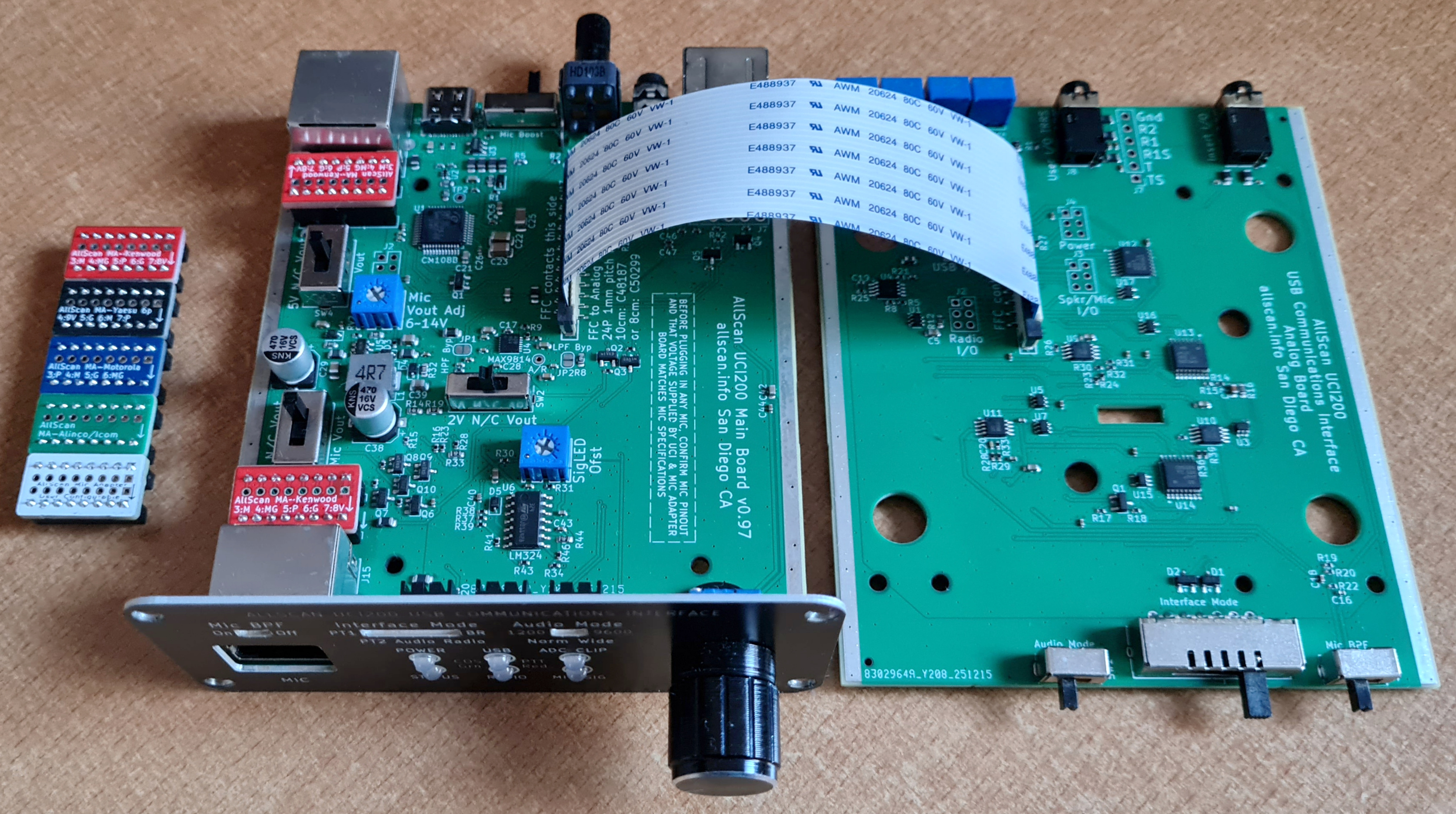
The UCI200 provides the following interior controls:
- Mic Vout Enable: This can be set to enable a mic supply voltage of 5V, 6-14V, or N/C. Be sure to confirm what supply voltage the mic you are using requires and properly configure this switch before plugging in the mic. Note that most ham manufacturers list their mic jack pin numbers in reverse order from electronics and telecommunications industry standards for RJ45 and RJ12 jacks thus it should not be assumed that the pin numbers on various manufacturer schematics or other documents are correct. See the notes in the Mic Adapter Boards schematic linked above for more details. Usually though when ordering a UCI200 you will already know what mic and radio you plan to use and I'll preconfigure these settings for you
- Aux Vout Enable: Same as above but for the Aux Mic / User I/O RJ45 jack
- Mic Vout Adjust: Sets the 6-14V mic supply voltage DC-DC converter output Voltage. The DC-DC converter is only enabled if one of the Mic Vout Enable switches it set to the 6-14V position. The UCI200 can support supplying 5V to one RJ45 jack and 6-14V to the other, or either Voltage to both
- Mic Bias Enable: This can be set to enable a mic bias voltage of 2V, 6-14V, or N/C. Most ham mics do not require bias voltage. See the Mic Adapter Boards schematic and mic schematic for more details
- SigLED Offset: Calibrates the Mic Signal LED driver circuit to match the voltage drop of the LED. This is calibrated before shipping and should not need to be adjusted
Audio Processing
The UCI200 integrates 3 previous AllScan products into 1 – the UCI120, URI110, and MA1. The mic audio processing features of the UCI120 are discussed in detail on the UCI120 Product Page. To summarize, the UCI200 mic audio processing ensures that mic audio will have equal or better audio quality and dynamics as even the best ham mobile radio equipment or repeater systems.
The Mic Gain Adjust knob should initially be set fully clockwise (0dB) and the Mic Boost switch at 0dB, and those should be changed only if needed for a particular mic that has higher or lower output levels.
Mic Options
The UCI200 supports a very wide range of microphones, including those supplied with higher-end mobile radio transceivers such as the Kenwood TM-V71A, Yaesu FT-8800R, FTM-300DR and many others. It also supports headsets, dynamic mics, 12V condenser mics, desk mics, as well as line level audio sources through the Insert I/O jack. Small Mic Adapter boards enable the UCI200 mic jacks to be reconfigured in minutes to support mics from all major two-way radio equipment manufacturers.
The mics supplied with most mobile radios do not have an actual DTMF encoder, ie. they send serial data to the radio and the radio then generates DTMF audio. As a result these mics will not be able to send DTMF tones to the USB host application. DTMF commands can still be sent to the host app eg. ASL from an HT with the UCI in Radio or Bridge mode, or from the AllScan, AllMon or Supermon web apps or similar smartphone apps, or via SSH and the Asterisk CLI, scripts or tune menu commands.
Mics with a built-in DTMF tone encoder such as an Alinco EMS-79 or Motorola HMN1037B can be used, but DTMF commands from a mic are rarely if ever needed with AllStar. Commands can easily be executed through the various aforementioned apps – which tend to be much easier to use than having to remember various DTMF commands and node numbers, and this prevents the issue of remote connected systems being kerchunked when executing commands.
Speaker Options
Any 3 - 8 Ω speaker should be fine but for the best audio quality I would recommend a mobile speaker from Icom, Kenwood or Yaesu such as an SP-35 or MLS-100 which are around $30 or so. Or Heathkit, Motorola, Kenwood and many other vintage speakers often sound excellent and can be easily found for $25~$50.
The UCI200 speaker amp has plenty of volume for most environments, but for louder environments eg. driving on the highway with the windows down you may need something a bit louder. The UCI200 will output 2.5W @ 4Ω and 1.5W @ 8Ω, and the 3.5mm User I/O jack can be used to go into any boombox, car or home stereo Aux In jack or powered speaker.
AllStarLink Setup Notes and Required Settings
ASL's USBRadio driver provides some useful features vs. SimpleUSB including wider filter bandwidth settings and better limiting functionality, and is thus highly recommended when using flat audio. USBRadio driver supports one output having voice only and the other output also having CTCSS tones encoded, which may be preferable if you wanted to have ASL do the CTCSS encode, however because the UCI200 does not have an internal CTCSS encoder it is probably better to have the radio do the CTCSS encode and tone squelch so that CTCSS will be properly handled when in the Pass-Thru interface modes.
Level settings of 999 are recommended for both txmixaset and txmixbset to ensure the Volume knob and Radio Tx Level trimmers have the widest range of control, then rxmixerset should be set to around 600, with the UCI200 Mic Gain and Radio Rx Level controls used to then further adjust Rx audio levels.
Enable USBRadio channel driver using asl-menu, or by setting rxchannel = Radio/[Node#] under the [Node#] stanza in rpt.conf and load = chan_usbradio.so in modules.conf. Also be sure to set duplex=3 in rpt.conf. The SimpleUSB driver may also work fine but USBRadio is just as simple to set up in this case.
Settings for Radio in 9600 Mode
Make the below settings in usbradio.conf:
rxboost = no
txctcssdefault = 88.5    ; Default Tx CTCSS tone
rxctcssfreqs = 88.5,97.4 ; List of Rx CTCSS tones to accept
txctcssfreqs = 88.5,97.4 ; List of Tx CTCSS tones that can be used
carrierfrom = usbinvert
ctcssfrom = no
rxdemod = flat
txboost = yes
txprelim = yes
txtoctype = notone
txmixa = voice      ; Left channel, routed to UCI Speaker Out
txmixb = voice      ; Right channel, routed to UCI Mini-DIN-6 Out
rxlpf = 1
rxhpf = 1
txlpf = 1
txhpf = 1
duplex = 1
clipledgpio = 1
legacyaudioscaling = no

[NODE#](node-main)
rxmixerset=600  ; Adjust using tune menu so that Rx levels peak no higher than 5KHz
txmixaset=999
txmixbset=999
rxvoiceadj=1.0  ; Should be a good starting point but may need adjustment in the tune menu
The UCI Audio Mode switch should be set to 9600.
Settings for Radio in 1200 Mode
The settings in the above section should be used with exception of the below parameters:
rxdemod = speaker
txprelim = no
txlimonly = yes
The UCI Audio Mode switch should be set to 1200.
To enable easy switching of Speaker/Flat audio in ASL, DTMF commands could be set up to call a script that copies eg. either usbradio-1200.conf or usbradio-9600.conf to usbradio.conf and then restarts Asterisk. This could also potentially be done by connecting the UCI's Audio Mode switch output to eg. GPIO2 and then set up an event in ASL to call the above script.
ASL3 Clip LED Support
The UCI200 supports the ASL3 ADC Clip Detect feature. To enable this be sure you are running ver. ≥3.0.5 and that you have the "clipledgpio = 1" line in simpleusb.conf/usbradio.conf. The ADC Clip Detect feature checks the raw ADC data stream for sequential clipped samples. If the Clip LED ever illuminates during normal use be sure to reduce the Mic Gain Adjust knob or Mic Boost switch settings and/or the Radio Rx level setting trimmers, or the ASL rxmix setting. AllStar audio levels should ideally have at least 3-6 dB of headroom between maximum audio levels and where clipping starts to occur.
General Setup Steps
I recommend the following steps to set up a UCI200, test each mode and calibrate the various audio level settings:
- Confirm the UCI has the correct Mic Adapter boards and internal settings for the mic you will be using. This should have been confirmed when you placed your order but it's good to double-check that these are all correct, and that the pinout of the mic you'll be using does in fact match the pinout shown on the AllScan Mic Adapter boards schematic. Plug the mic into the front RJ45 jack, and plug a speaker into the Speaker jack. Set the Volume knob to about 20%.
- Set up a MiniPC/RPi with ASL3 as described above and in my How-To guides. I recommend initially using 1200 Audio Mode only and following all the below steps in 1200 Mode. Once that is all working well, you can then try 9600 mode if desired and then repeat the below steps.
- Plug in the UCI, power on the MiniPC and confirm the Status LED is blinking, which indicates ASL is communicating with the UCI.
- Set the Interface Mode switch to Audio (ie. Radio-less mode). Key up the mic and confirm the Mic Sig LED lights up yellow (Red PTT + Green Mic Signal level) and that ASL then keys up (USB Green COS LED comes on) and you hear a courtesy tone after unkeying. Then enable parrot mode or connect to a parrot node (eg. 55553) and check that your mic audio sounds good.
- Configure the radio as described here. Connect a Mini-DIN-6 cable between the UCI and the radio. Connect an RJ45 or RJ12 cable between the UCI Aux RJ45 and the radio's Mic In jack. Be sure you have ferrites with one turn of the cable on the USB cable and all cables between the UCI and radio.
- Switch the Interface Mode to PT1 and confirm that the mic works as it should with the radio and you are able to use local repeaters and use the mic keypad to control the radio.
- Switch the Interface Mode to Radio, then talk into the mobile radio from an HT and confirm you are able to use AllStar on the HT. You will likely need to adjust the Rx and Tx Level trim pots on the back of the UCI until your Rx and Tx levels to and from the HT sound good. Be sure to watch the ADC Clip LED on the UCI and if it ever lights when talking into the node then reduce the Rx Level trimmers and/or reduce the rxmix setting in ASL. Then try changing channels on the HT and confirm the Rx level from the node is about the same as the audio levels from local repeaters. Or you can use a service monitor or SDR to check the deviation from the mobile radio.
- Once you have spent some time using the Radio-less and Radio modes and are comfortable that all I/O levels have been set optimally, you can then try Bridge mode which enables all audio paths. You can then talk into the mic or into an HT, and that audio will go into AllStar, and if parrot mode is enabled will then play back to the speaker and through the radio. Some further iterative adjustments to various levels may be required to get the optimal mix of levels for each audio source to each audio destination.
If you have any questions, feel free to email me at the email address shown on the main page, and let me know as much detail as possible about your setup, settings and steps followed.
Specifications
USB Audio IC
The CM108B USB audio controller/codec IC is a versatile and cost-effective USB audio solution providing CD-quality 16-bit 48Ksps audio (2 output channels and 1 input channel).
- The CM1xxB usable input range (supporting full ADC dynamic range) is -18 to 6 dBVrms, which corresponds to ASL rxmixerset values of 999 to 325, and IC mixer gain settings of 34 to 11 (1dB steps)
- CM1xxB ADC stated SNR is 90dB, DAC SNR is ≥93dB
- CM1xxB DAC ±3dB frequency response is 20–20K Hz
- CM1xxB ADC ±3dB frequency response is 100–20K Hz, but its response below 100Hz is usable and can support the lowest CTCSS tones, though this is not needed anyway when CTCSS decode is done in the radio
For more details see C-Media CM1xxx Spec Sheets.
The UCI200 uses both the Left and Right audio outputs of the CM108B IC. The Left output is routed to the UCI200 Speaker ouput and the Right output is routed to the Mini-DIN-6 output.
Mic Jacks
The UCI200 provides 2 RJ45 (8-pin modular) jacks, each of which are connected to internal headers that accept AllScan Mic Adapter boards. These small 10x18mm adapter boards support the use of virtually any brand and model of microphone from all major ham radio manufacturers as well as supporting Motorola mics, dynamic mics, 12V condenser mics, headsets, computer mics, etc.
Generally the UCI200 will be used with a mobile radio and the mic supplied with the radio will then be plugged into the front RJ45 mic jack on the UCI200. The back mic jack then gets connected to the radio's Mic In jack with a short RJ45 or RJ12 cable. With an adapter board for that mic brand/type plugged into the UCI200's internal headers for each jack, the mic audio, ground, PTT and power supply lines then connect to the appropriate lines in the UCI200, and those and other lines from the front mic jack are passed through to the radio through the back RJ45 jack. The PTT line is only passed through to the radio Mic In jack when in PT1 mode; in other modes PTT is passed through to the Mini-DIN-6 jack. The mic's button press data lines are always passed through however thus it is always possible to use the mic to change channels, frequencies, use other programmable function keys, or send DTMF tones when the radio is transmitting. (Even though most of the UCI200 interface modes use the Mini-DIN-6 jack for audio to & from the radio, most radios will still encode DTMF tones entered on the mic keypad.)
Headset / Speaker-Mic / OHIS Connections
Speaker-mics and many headsets have an electret mic element requiring a ~2 Volt bias voltage on the mic audio line. The 3.5mm User I/O jack can directly support an electret mic with bias voltage, PTT, and speaker audio output, or the AllScan MA-OHIS adapter board can be used on one of the RJ45 jacks and the speaker mic or headset wired to an RJ45 plug with OHIS pinout. Speaker mics designed for Kenwood/K1 HTs (3.5mm & 2.5mm jacks) will work great as they provide a standard PTT to Ground output. To connect a K1 speaker mic would require an adapter cable to go from K1 3.5mm & 2.5mm jacks to a 3.5mm TRRS or RJ45 plug.
Revision History / Schematic Notes
For schematics of earlier versions see the AllScan-Products GitHub repository. Note that the version number is shown on the PC Board. (The back panel version number refers to the top-level product assembly.)
Node Setup & Management
See the How-To Guides on the Main Page for details on how to set up an AllStar node. I highly recommend Dell 3040 MiniPCs and ASL3 along with my AllScan web app for managing node connections and favorites.
Full-Duplex Notes
Be sure to read the Full-Duplex Communication Benefits section in my How-To Guides for important notes on the benefits of full-duplex on AllStar.
Conclusion
The UCI200 brings an entirely new level of features and flexibility to AllStar and other ROIP apps. A thorough and uncompromising approach was taken in the UCI200 development, resulting in a highly flexible platform that can accommodate a wide range of applications. For more info see the Products page.